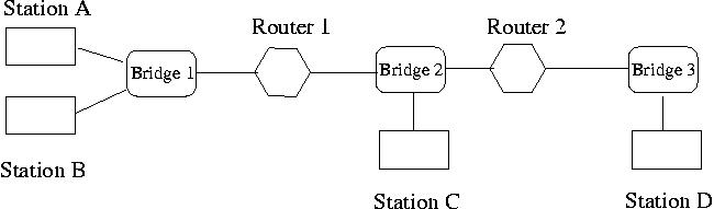
Figure 1. A simple IP network.
We consider a star-wired LAN topology where each station is directly connected to a common central node, called a transparent bridge or bridge in short (or switch). Each station is connected to the bridge through one of its ports, thus a bridge with n ports can connect n stations in total. When a bridge is first plugged, it repeats a packet (ethernet frame) it receives from one station (via one of its ports) to all the other stations attached to it, i.e., by retransmitting the packet through all the ports except for the one from which it receives the packet. This enables every station to hear the transmission from any other station connected to the bridge. Through self learning, the bridge will gradually learn the location of the stations on the LAN and only direct the packet to the necessary segment of the LAN.
IP routers interconnect LANs to form a virtual IP network. Any pair of stations in this virtual network can communicate with each other using the Internet Protocols. Stations and routers (or more precisely, the interfaces through which they are attached to the internetwork) are assigned globally unique IP addresses. IP uses a table-driven, hop-by-hop datagram delivery model. Each datagram is attached an IP header with appropriate source and destination IP addresses. Routers (and in the very first hop, stations) are responsible for delivering datagrams to their next-hops towards the destination. This hop-by-hop packet forwarding is based on some forwarding (routing) table. All the routers in the internetwork will run some routing protocol to create a local forwarding table for its own.
A station can transmit a packet to another station. Before it transmits the packet, it needs to add a packet header. The two most important fields in the header are source address and destination addresses. A station should also accept a packet sent by another station which is addressed to it while discarding any other packet which it receives but is not addressed to it.
Figure 1 presents a simple IP network, where we have three LANs, realized through three bridges, Bridge 1, 2, 3, respectively. Router 1 interconnects LAN 1 and LAN 2, while Router 2 interconnects LAN 2 and LAN 3. On LAN 1, we have two stations, Station A and Station B. LAN 2 and LAN 3 each have a single station, Station C and Station D, respectively. In this configuration, Station A and Station B can communicate with each other directly through Bridge 1. When Station A sends a message to Station C, Router 1 will forward this message from LAN1 (Bridge 1) to LAN2 (Bridge 2) by consulting its routing table. Similarly, when Station A tries to send a message to Station D, Router 1 will forward it from LAN1 to LAN2, and Router 2 will forward it from LAN2 to LAN3 based on the packet destination IP address, i.e., the IP address of Station D.
As you know, the paradigm used in socket programming is a client-server model. In our network emulation model, we will have a bridge act as a server and stations (routers) attached to it as its clients, and the physical links between the bridge and a station will be emulated by a connection-oriented TCP socket connection. Note that you always have to run a bridge first before running a station (why?). A client has to be aware of the whereabouts of the server in any client-server model (a common approach is to have the server use a well-known port). Here we make lan-name one of the command line arguments for the bridges, so that stations and routers on the LAN know where to look for the bridge information. There can be only one bridge for a given lan-name. Once a bridge is ready to listen, it stores its IP address and the port by creating two files (or symbolic links) in its directory (assumed that both bridge and station are invoked from the same directory which shared across all the machines in the emulation) namely .lan-name.addr and .lan-name.port (this is just one way of sharing information between a server and a client). Given a lan-name, a station, by reading these two files, knows the complete address of the bridge.
Program Interface
A bridge takes two command line arguments lan-name and num-ports. We have already explained the role of lan-name. A bridge has to make sure that there is no other bridge already existing for the same lan-name. The argument num-ports specifies the maximum number of stations (and routers) that can be attached to it. So a bridge has to keep track of the number of stations currently connected to it and accept a connect request only if that number is less than num-ports.
usage : bridge lan-name num-ports
The first thing a bridge does is to get ready and wait for connection set-up request from a station (or router). The second thing for a bridge to do, when it is first started, is the repeating function of a bridge. Namely, when receiving a packet from one of its ports, the bridge must send it to all the other stations through the ports they are attached. The third thing is the self learning function. Since we allow a station to attach to a bridge at any time (as long as there is a port available at the bridge), a bridge must still wait for possible connection request from a client while performing the repeating function by receiving packets from a port and sending them out to all other ports. In other words, the bridge must monitor several events that can occur at any of its ports. In order to achieve this I/O multiplexing, you may need to the select() function.
Program interface
A station takes three arguments, interface, routingtable, and hostname. All of them are file names. The file hostname contains the mapping between host (interface) names and IP addresses. For example, the following is an example line taken from a hostname file,
A 128.252.1.254
which states that station A's IP address is 128.252.1.254. This provides some similar functionality of DNS.The file interface contains the (NIC card) interface information of the station. The following is an example line taken from an interface file,
A 128.252.1.254 255.255.255.0 00:00:0C:04:52:27 cs1
which states that, the (station) interface name is A, its corresponding IP address is 128.252.1.254, and the network mask is 255.255.255.0. The fourth field is the Ethernet address of the NIC card. The last field is the name of the LAN (bridge) that the (station) interface is connected to.The file routingtable contains the routing table that the station will use when it sends a message to another station. One example of this file's content is,
128.252.11.0 0.0.0.0 255.255.255.0 A
0.0.0.0 128.252.13.38 0.0.0.0 A
The first column is the destination network prefix, the second one is the next hop IP address, the third the network mask, and the last is the network interface through which the next hop can be reached.
usage: station -no interface routingtable hostname
where -no specifies that this is a station instead of a router.
Functionalities
Besides the connection set-up procedure of a station (which emulates the action of plugging a station to a bridge), the only functions of a station are to send messages keyed in from the keyboard and accept messages addressed to this station by displaying the messages it receives and the name of the stations sending the messages. A packet may traverse many hops before reaching the destination. At each hop (either a station or router), we need to determine which router (or station) is the next hop based on the destination IP address and the local routing table.
A router is like any other station, except that it may be connected to more than one bridge and they forward packet that is not destined to it. It gets attached to all the bridges corresponding to each lan-name specified in the interface file.
usage : station -route interface routingtable hostname
Wherer -route indicates that this is a router.
After a router receives a packet (ethernet frame) addressed to it, It first decapsulates the ethernet packet, and then passes it to the IP protocol. The IP protocol consults its routing table to determine the next hop that the packet should be sent to. Before sending the packet out, it will encapsulate the IP packet in an ethernet frame..
NOTE: In the first phase, a router gets the routing table from the file, i.e., the routing table is populated manually. In the second phase, a router needs to run a routing protocol to learn the network topology and compute the short paths to each destination network and fills the routing table accordingly.
In the first phase of the project, you are asked to implement transparent bridges, ARP, IP, and UDP.
In this phase, you need to implement TCP and OSPF.
In the following, we will describe them in detail one by one.
After a router starts, it will send a Hello message to the all-routers IP address. For example, consider a network IP address 128.252.1.0/24, the all-routers IP address is 128.252.1.255. The hello message includes (at least) the following information:
 ospf_msg_type
 router ID
 sequence number
 number of neighbors
 list of neighbors
where ospf_msg_type is OSPF_TYPE_HELLO; router ID is 4 bytes (IP address); sequence number is used to indicate if there is something new at the sending router (see below); number of neighbors indicates how many neighbors the router knows now; list of neighbors is a list of the neighbors' router IDs.
When a router receives an OSPF message, it checks the ospf message type. If it is a hello message, it reads out the router ID information, and checks to see if this is a new neighbor. For this purpose, each router maintains a neighbor list.
ospf_msg_type
Optional Fields
When a router receives a helloAck message (see above for the format), it will respond back an OSPF_TYPE_LSA_UPDATE message, this is discussed below.
A router will send out an OSPF_TYPE_LSA_UPDATE message to another router after it hear the helloAck message from that router. The format of the OSPF update messsage is
    ospf_msg_type
    router ID
    sequence number
    number of neighbors
    a neighbor router ID
    distance to the neighbor
    ...
    number of directly connected subnet (LAN)
    a subnet (network) IP address
    network mask
    disttance to the subnet
    ...
    optional field
where ospf_msg_type is OSPF_TYPE_LSA_UPDATE; router ID and
sequence number have the previous meaning. Note that this router ID is
the router identifier of its own; the number of neighbors
indicates how many neighors follow in the messsage. Following this
information is a list of neighbors and their distance to this router. We
assume the distances to be 1. Also included in the update message is
list of LANs that the router connects to, and the distances (assumed
to be 1). Optional field has the following format:
    router ID
    sequence number
    number of neighbors
    a neighbor router ID
    distance to the neighbor
    ...
    number of directly connected subnet (LAN)
    a subnet (network) IP address
    network mask
    disttance to the subnet
    ...
    optional field
Its format is as same as above, however, this set of information is not the
one of the sending router. Instead, it is the information of other routers
in the network that are currently in the link-state database of the
sending router. This optional field is attached only when a router
detects a NEW router. The purpose of this optional field is to speed up the
materialization of the link-state database of the new router.
After a router receives an OSPF_TYPE_LSA_UPDATE, it records down the information contained in this packet into a link-state database including the router ID, its neighbors and the distances, its directly conntected subnet and the distances. It will also floods this update message out to other routers.
Note also that, when a router detects a new router (heard a HELLO message from a new router), after it has sent back HELLOACK and received update message, it will immediately send HELLO message to the new router instead of waiting the timer indicating when to send next HELLO message to expire. In this way, the new router will get the network topology faster. (Note also, as we will see later, the time interval to send out HELLO message in the MAINTAINANCE phase is relatively long.)
Note that, a router needs to make sure that there is no loop. That is, if this update is about a new router, or the sequence number is "newer" than the one in its local link-state database, the router will forward it; otherwise, it should just ignore this update message. Note that if optional field is present in the update message, the receiving router may change the content of the update message before forwarding the update the packet (namely removing some optional field which is related to the routers that are already in the local link-state database).
destinationIPAddress nextHopIPAddress networkMask interface
where destinationIPAddress is the IP address of the destination (network), hextHopIPAddress is the IP address of the next hop (where the router should forward a packet to, remember that this information is contained in the neighbor list), networkMask is the network mask; and interface is the name of the interface from which the packet should be sent out.
Now let us move on to the MAINTAINANCE phase. After the LEARNING phase, a router has computed its routing table based on the link-state database. From now on, it moves on to the MAINTAINANCE phase. In the MAINTAINANCE phase, it will again periodically send out HELLO message to the ALL-ROUTER IP address, with a relatively long time interval, say 10 seconds. If a router does not hear HELLO or HELLOACK message from a neighbor for certain time interval, say 30 seconds, it considers this neighbor is dead. It will re-compute the routing-table and floods this information out to other neighbors by the update message. Note that, whenever a router detects some changes of its neighbor information, the sequence number will be increased by 1 (mod (the maximum sequence number +1)) so that other routers know that this update information is newer.
We only grade the part of the code that works