Software Requirements Specification Document
Software Requirements Specification (SRS)
IEEE Std 830 is a "recommended practice" for software
requirements specification documents.
The IEEE has a different standard for a "Software Requirements
Document" (SRD), which is IEEE/EAI 12207.1-1997. If you look in the table
at the back of IEEE Std 830-1998 you will see the cross reference
tables in Appendix B, showing that these are consistent with one another.
Standards are periodically updated, so there are several
versions of IEE STd 830, including IEEE Std 830-1983, -1993, and
-1998. These standards also allow some room for discretion.
It therefore follows that you may see several different suggested
table of contents outlines for SRS documents purporting to
be based on this standard.
The IEEE holds the copyright to these documents and sells
copies to support its operations. However, you can find copies
on the Web. I found one by Googling "IEEE STD 830 pdf":
http://cs.uwlax.edu/~riley/CS741Sum10/Examples/830-1998IEEE.pdf.
Table of Contents
The following is on example of an outline for an SRS.
1.  Introduction
      1.1 Purpose
      1.2 Scope
      1.3 Definition, Acronyms, or Abbreviations
      1.4 References
      1.5 Overview
2.  General Description
      2.1  Product Perspective
      2.2  Product Functions
      2.3  User Characteristics
      2.4  General Constraints
      2.5  Assumptions
3.  Specific Requirements
3.1  Functional Requirements
      3.2  Interface Requirements
      3.3  Data Requirements
      3.4  Behavioral Requirements
      3.5  Design Constraints
      3.6  Standard Compliance
      3.7  Environmental Definition
      3.8  HCI
System Requirements Specification

SRS Characteristics
- Correct
Specifies every true requirement known at that time and no incorrect specifications - no
wrong data
- Precise
Remember this must eventually turn to executable code; fuzzy words in requirements
are not acceptable
- Unambiguous
Each requirement has only one interpretation
- Complete
Everything included behavior (methods, use cases, systems, subsystems, business rules)
and data (objects, attributes)
- Verifiable
Is the software built what was specified in the SRS?
- Consistent
Are there any conflicting terms, characteristics?
- Understandable
Are formal specifications understandable? Are informal specifications understandable?
- Modifiable
Requirements need to be easily modified when specifying, designing, coding, implementing
- Traceable
Can I locate the SRS origin of every software component?
- Design Independent
SRS should not specify a particular design, or overconstrain the design
SRS
- Section One
- Overview document for executives describing the system from a management perspective
- Section Two
- General Description describing the system from a user and system perspective in general terms
- Section Three
- Detail document for users and developers describing the system in detail terms
Section 1 - Overview
- Overview of the project describing the purpose of the proposed system.
- Defines the scope of the proposal.
- Defines any needed terms.
Small examples of each part are set in italic font.
1.1 Purpose
The Purpose section states the goals and objectives of the
system. Goals have to do with the general purpose of a system.
Goals are fuzzy and non measurable. Goals are decomposed into
objectives. Objectives are finite and measurable. You know when
you reach them.
example:
The goal of this project is to reduce the time and lines for
students receiving financial aid. Objectives are to automatically
verify financial aid request for correctness and completeness,
track request within FSU, allow on-line access for students to the
department of education, allow on-line notification of problems to
students for quick correction, and ...
The benefits of this
project are increased student moral... (tangible...,
intangible...)
1.2 Scope
The Scope section defines the boundaries of a system. These
include what is inside the system - what will be designed and
programmed.
example:
The scope of this project includes initiation of financial
aid, verification of aid packet, tracking of request within FSU,
access to DOE tracking, ...
The resulting products of this
project include on-line tracking screens, on-line student
verification and notification, ... (generally not individual
I/O)
The people involved in this project include (names and
titles) ... The production of this document was done by
...
1.3 Definition, Acronyms, or Abbreviations
As you begin to define a system, you will encounter words which
need definitions and general usage acronyms. These should be
documented for new personnel and for clarity of all concerned
parties.
example:
FSU - Florida State University
CS - Computer Science
MSES - Masters in Software Engineering Science
DOE - Department of Education
...
1.4 References
example:
Many references may be used to define existing systems,
procedures (both new and old), documents and their requirements,
previous system endeavors. These references are listed here for
others.
example:
DOE document #DOE4564 -Description of DOE Tracking System ...
1.5 Overview
The Overviw section defines the organization of the entire
document. It will lay the framework for reading the document.
example:
The remainder of this document is organized as follows.
Section 2 describes the ... and explains ... .
Section 3 discusses ... and specifies ... . ...
Section 2 - General Description
- Overview of the system and its relationship with other systems.
- "Shall List" of the functions
- User behavior characteristics
e.d., users, operations ...
- System constraints (time, space, money)
e.g., hardware, tracing, accounting, compliance standards, ...
- Additional requirements
e.g., security, reliability, mobility, availability, performance, external interfaces
- Assumptions
2.1 Product perspective
example:
This product ... will be the responsibility of the XXX group
within the organization. It will do the reporting for the four xxx
departments. It serves as a xxx vendor invoicing sytem for the
xxx accounting system xxx. It interfaces with the xxx
organization and xxx financial system ...
We estimate it will add xxx number of transactions on the PC
systems in the district offices and xxx number of transactions on
the mainframe during peak hours of daily processing. It will add
2 hours of batch processing in the evening.
The environment of the system includes ORACLE database, Unix
operating system, TCPIP communication system.
2.2 Product Functions
This section lists the major functions of the system. James Martin documented the major business
functions of all business in his technique on Information Strategy. These include items such as
accounts receivable, accounts payable, sales, administration, etc. In this section you should note
which major business function is impacted and the minor functions. The section decomposes the
function until a verb is encountered to name the processes of the functions.
This section also includes the "shall list", which specifies what the system
should do. Each item in the list is a statement of the form "The system shall
...".
example:
This product builds a system under the major business function of financial management. It is
under the sub-function of accounts receivable. It includes the process named issue bills.
The system shall:
accept charges to a persons account.
accept payments to a persons account.
report amount of charges per month, year, and location.
report amount of payments per month, year.
bill persons for amount due, over 30, over 60, and over 90.
adjust accounts.
...
2.3 User characteristics
- Enumerate the users involved with the proposed system.
- Describe the responsibility of each type of user involved.
example:
The users of this system include the business clerks who
make charges to a person's bill, the data entry operators who make
payments to the bill, the administrators at the district offices
who make inquiries against a patient's bill, the managers who
review the reports monthly, and the accountants who make
adjustments.
The clerks will use an automated credit card debit machine and
will be trained on this type of equipment. The data entry
operators will use a key to disk machines. The administrators
will use a PC intelligent terminal. The managers will use Excel
type reporting. The accountants will use a PC
intelligent terminal.
2.4 General Constraints
In this section, the constraints of the system are listed.
They include hardware, network, system software, and software
constraints. It also includes user constraints, processing
constraints, timing constraints, and control limits.
example:
The constraints of this system include the following:
The hardware must be secured from any internet access.
The software must be:
DB2 database on mainframe and PC
MVS operating system on the mainframe
Windows NT on PC's
TCPIP for PC communications
SNA Network
Audit functions include the State Audit Control Board.
Batch processing must be limited to 2 hours during evening.
On-line processing must not impact the current schedule.
...
2.5 Assumptions
This includes assumptions made at the beginning of the
development effort as well as those made during the
development.
example:
The assumptions are that:
This system will not need any more or less personnel.
All existing personnel are trainable.
...
Software Specification Tools - Data Dictionary
- an important tool for software development
- one of the required components of the specification document
- also known as "encyclopaedia" or "repository"
- may contain many kinds of information
- interfaces (inputs, outputs, external interfaces)
- data entities
- data elements (attributes)
- use cases
- classes
Data Dictionary Entry Components
- Name (of the item)
- Type (use case, input, output, external interface, class, class or entity
component (attribute), class operation ...)
- Description
- Compositional definition using DeMarco notation
- other information, as appropriate
Names may be overloaded, but there must be only one entry
with the same name and type.
DeMarco Notation
Can be used to specify items in data dictionary
| ... = ... | | is composed of |
| ... +... | | and |
| [ ... / ... ] | | either/or |
| { ... }n | | repetitions (n times) |
| ( ... ) | | optional |
| * ... * | | comment |
This is reminiscent of regular expressions, but what are the differences?
Data Dictionary Entries
should include:
- Name of the item
- Type (use case, input, output, external interface, class, attribute, class operation ...)
- Description
- Composition definition using Demarco notation
- other data as needed
Overloading names is OK,
but there should be ONLY ONE entry with the same name AND type.
Example of composition using DeMarco:
SRF = student SSN + student name (student address + classification) + {class information}
class information = class prefix + class number + section number + reference number +
(building number + room number)
SRF = student registration file entry
Section 3 - Specific Requirements
Small examples are given for the various subsections.
3.1 Functional Requirements
example of Data Dictionary for shall list:
| Item Name | Type | Description |
|---|
| 1.1 | shall | The system shall allow editing of data. |
| 1.2 | shall | The system shall allow saving of needed data. |
| 1.3 | shall | The system shall allow displaying of data. |
| 1.3.1 | shall | The system shall allow displaying of student data. |
3.2 Interface Requirements
- Interface ID (inputs, outputs, external inputs/outputs)
- Interface Example
- Interface Data Dictionary
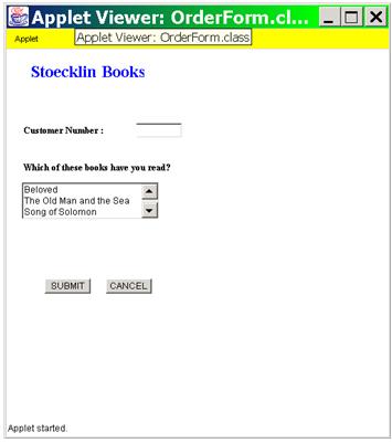
3.2.1 Interface Requirement Example - Book Order Form
Data Dictionary for Interface
example:
| Item Name | Type | Descripton | Constraints | Environment |
Security | Composition |
BookOrderForm | input Screen | This screen allows input of an order for book(s). | none | Web |
none | customerNumberLabel + customerNumberTextfield + booksListLabel +
booksList + submitButton + cancelButton |
Data Dictionary for Interface (the elements)
example:
Data Dictionary for Interface (the elements)
example:
| Item Name | Type | Descripton | ... | Constraints | Environment | Security |
|---|
| booksListBox | ListBox | 20x100, 3 entries | | none | Web | none |
| booksListBoxLabel | Label | "Which of these books have you read?" | | none | Web | none |
| bookName | String(20) | Name of a book | | none | Web | none |
| cancelButton | Button | Button to cancel entry of screen | | none | Web | none |
| customerNumber | Integer(4) | Number assigned to a customer upon
their first order through the customer entry screen | | none | Web | none |
| customerNumberLabel | String | "Customer Number:" | | none | Web | none |
| customerNumberTextfield | Textfield | Textfield allowing entry of
customer number | | none | Web | none |
| submitButton | Button | Button to submit data from the screen | | none | Web | none |
Another example of elements of a student screen
| Item Name | Type | ... | Composition or Definition |
|---|
| studentAddr | Composite | ... | studentAddrStreet +
studentAddrSecondLine + studentAddrCity + studentAddrState + studentAddrZip |
| studentAddrZip | Long Int (5) | ... | student US zip code |
| studentAddrZipExtended | Int (4) | ... | student US zip extension |
| studentFirstName | String | ... | 20 characters |
| studentName | Composite | ... | studentNameFirst +
studentNameMiddle + studentNameLast |
3.3 Data Requirements
- Entity Relationship Diagram (ERD)
- ER Data Dictionary
Entity Relationship Diagram
Entity Relationship Attribute Diagram
ER Data Dictionary
example:
| Item Name | Type | Descripton | Constraints | Environment |
Security | Composition |
|---|
| Student | Entity | A student, alumnus, or applicant. | none | Client Side | Only Admission Department personnel |
ssn + studentName + studentAddr + studentYearEntered + ... |
3.4 Behavior Requirements
- Use Case Diagrams + Data Dictionary for Use Cases
- Process Diagrams + Data Dictionary for Process
- Class Diagrams + Data Dictionary for Classes
- State Transition Diagrams or State Charts
Data Dictionary for Use Cases
example:
| Item Name | Type | Constraints | Environment | Security |
Composition or Definition | Site | Shall Link |
|---|
| Entry of Admission Student |
UseCase | none | Client Side | Only Admissions Department
Personnel | ssn + studentName + studentAddr + studentYearEntered + ... | all | 1.5 |
Class Dictionary
example:
| Item Name | Type | Constraints | Environment | Security |
Composition or Definition | ... |
|---|
| Student | Class | none | Server Side | Only
Admissions Department personnel | TBA | ... |
Process Diagrams
Several kinds of diagrams may be useful in modeling the
interactions of the system to be built with its users and
other entities in its environment.
- Data Flow Diagrams
- Control Flow Charts
- Work Flow: IDEF3, IDEF0
- State Charts
- Use Case Diagrams
Some of these same diagrams may be useful later, in the
design phase, to model the functions and
interactions of the components into which the design has
decomposed the system.
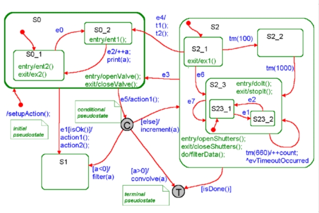
State Charts
State diagrams or state charts are also used to describe processes.
See also the notes on statecharts in the Chapter
12 notes.
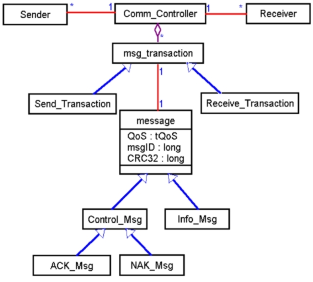
UML Object Diagram for Comm. Controller
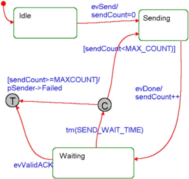
UML State Chart Detail for Send_Transaction
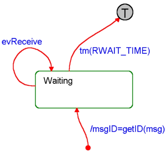
UML State Chart Detail for Receive_Transaction
More Complex UML State Chart, With Nested States